TESTING
Testing Documents
Summary of Testing for Spring Quarter
The components being tested during spring quarter will be the suspension, chassis, and steering. Each of these sub-assemblies will be evaluated in various different tests determine whether they meet or fail the set requirements.
The test to be completed on the chassis will be the deflection test. A slow motion camera will be used to capture the results of the test as the force is applied while a measurement tool, such as a ruler, will be attached to the wall behind the chassis. The footage can then be reviewed to determine the results.
The suspension will receive two main tests; the drop test and ride height test. The performance of the drop test will be evaluated similarly to the chassis deflection as a slow motion camera will be used to see if the chassis impacts the ground after the drop. For testing ride height, the chassis will be placed under no load and a ruler will be used to measure the height from the bottom of the chassis plate to the road/surface.
Lastly, the steering tests will be completed. The goal for the steering is to achieve a turning radius of less than 5 feet. This will be analyzed by attaching a marker to the rear of the RC Baja truck as it drives over a large cardboard sheet. The marker will draw the arc of the turn and after a full 180 degree turn, the test will be stopped and radius will be calculated. Using a measurement tool such as a tape measure, the radius can be found using the drawn arc.
Test 1 - Turning Radius Test
Setup
Test occurred in the Hogue Fluke lab where two pieces of tape were placed 10-feet apart on a line (pictured to right).
Materials needed for the test were:
-
Tape Measure
-
Painters Tape
-
Pencil
-
Data Sheet
-
Table
To determine the turning radius of the device, the wheels were turned to the maximum angle in one direction. The throttle would then be applied only enough to allow the device to move. Once the device was oriented 180 degrees from its origin, the distance was recorded. To determine the radius, the value was divided by two. More details of the test are documented in the report.

Fig 1 - Tape placed 10-feet apart in Hogue Fluke lab

Fig 2 - Image showing the 10-foot mark for the turn radius test.
Materials
Testing Process
Test 2 - Chassis Deflection Test
Test occurred in the Hogue Machine Shop where the RC Baja device was supported by the two steel support blocks. Weight was then added to the center of the chassis and the deflection was measured using a straightedge ruler and feeler gauges.
Materials needed for the test were:
-
Feeler Gauges
-
Tape Measure
-
Pencil
-
Straightedge Ruler
-
6.5 lb Steel Blocks
-
5 lb Steel Base Block
-
Steel Support Blocks
To determine the deflection of the chassis, weight was added to the center of the and the deflection was measured using a straightedge ruler and feeler gauges.
Setup
Materials
Testing Process

Fig 3 - Image showing setup of chassis plate on support blocks for deflection test.
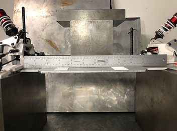
Fig 4 - Image showing the method used to measure deflection with straightedge ruler.
Test 3 - Drop Test

Fig 5 - Image of measurement for the taped 2-foot mark
Fig 6 - Slow-motion video of two angles of two separate drop tests showing chassis impact.
Setup
Test occurred in the Hogue Machine Shop where the RC Baja device was dropped from a height of 2-feet and the data was recorded using a camera.
Materials
Materials needed for the test were:
-
Tape measure
-
Painters Tape
-
Concrete surface
-
Phone/Camera
Testing Process
To evaluate the success of the test, the video that was recorded in slow motion was analyzed to determine whether the chassis plate made contact with the ground. From both of the engineers perspectives and from the sound during the test, the video confirmed that the chassis did make contact.