
ANALYSIS
Analysis
For analysis A-1, the angle at which the lower control arm must sit to achieve the requirement of two inches of ground clearance at rest. Analysis A-2 determines the thickness of the rocker arm by finding the stress about the rocker arm during the two foot drop test. For analysis A-3, the stress concentration about the pins of the rocker arm is calculated to find nominal pin diameter.
Analysis A-1
Lower Control Arm Length/Angle

Analysis A-1 is the calculation of the length and the angle necessary for the lower control arms. This angle is key to fulfilling the requirements of 2-inch ground clearance as well as the requirement to keep the chassis from hitting the ground in the drop test. This basic evaluation will allow the next analysis of suspension angle to have a neutral position. This angle will be critical in determining spring strength under the weight of the chassis itself. This dimension will be used in a later analysis.
Analysis A-2
Rocker Arm Thickness

Analysis A-2 illustrates the calculations made to ensure the thickness of the ABS material is able to withstand the bending forces involved in the suspension travel. With the two-foot drop test, the mass of the car was taken into consideration. With a requirement of 6 pounds and a safety factor of 2, the calculations were made with a weight of 12 pounds. Assuming such a high weight will allow the truck to handle better under more extreme conditions and loads. The design of the rocker arm is the critical point of failure for the cantilever suspension and more analysis will be needed to determine other forces such as shear, and forces at the pinned location.
Analysis A-3
Rocker Arm Pin Diameter

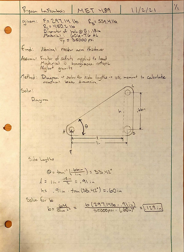
Analysis A-3 is the calculation to determine the stress about the pins in the rocker arm to find the nominal diameter. The analysis uses the dimensions from Analysis A-2 to solve for the bending stress about the pin at both ends. The load of 97lb is assumed to be accounting for the safety factor during the two foot drop. The safety factor applied was 2. Using these parameters, the diameter of the nominal diameter of the hole was found to be.054 in. This pin diameter is not a standard size and will likely be increased to achieve a more reasonable part design.

Analysis A-4
Spring Rate
Analysis A-4 demonstrates the calculation used to determine the suspension spring rate. The weight of the RC Baja truck chassis was considered and assumed to be 10 pounds and the drop force was expected to be about 80 lbf on each wheel. The spring rate was then calculated by determining a wheel travel of 1.5 inches upward which travels through the rocker arm ratio experiencing one inch of compression.
Analysis A-5
Tie Rod Length

Analysis A-5 depicts the steering system and calculations to determine the nominal tie rod length. These lengths were solvable due to the assumption of a .75 in servo arm. The diagram allowed the calculation to be simplified to a basic math problem which was also made possible by the assumption of having the servo in line with the spindles. The tie rod length gives a key piece of information to meet the requirement of a turning radius of less than 5 feet.
Analysis A-6
Force on LCA
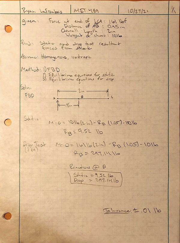
Analysis A-6 illustrates the forces acting on the front and rear lower control arms. The calculated force at the end of each arm was 80 lbf. This was then used to find the moment about the push-rod mount. This analysis is critical to fulfill the requirement of supporting the chassis weight during a two-foot drop.
Analysis A-7
Front LCA Thickness
_JPG.jpg)
Analysis A-7 uses the forces from Analysis A-6 to determine the nominal lower control arm cross section dimensions. The assumed height was .25 in and the material was 3D printed ABS plastic with a yield strength of 10690 psi. This calculation is important for the strength of the lower control arm and the drop test requirement. The test will put the lower control arms under a lot of loads which will create a point of failure if not accounted for.
Analysis A-8
Rocker Arm Thickness
_JPG.jpg)
Analysis A-8 covers the nominal thickness of the rocker arm under load as a solid body instead of a lever. This design gives the rocker arm much more strength under load and will allow force of the drop to be transferred to the spring. This part is key in maintaining structural rigidity and strength under the two-foot drop requirement.
Analysis A-9
Chassis Deflection and Brace Dimensions

Analysis A-9 depicts the 150 N force acting on the chassis which acts as a beam assumed to be pinned at both ends. The maximum allowed deflection of the beam is set at .100 in. The 1/8” thick chassis plate would deflect slightly more than the limit, so braces were developed and modeled to help support the load using the maximum deflection to determine the area. The purpose of this analysis is to meet the requirement of less than .100 in of deflection under 150 N.
LCA Pin Diamter
Analysis A-10
_JPG.jpg)
Analysis A-10 shows the calculation for pin diameter for the lower control arms. The force acting on this pin is in shear which allows the calculation to be made using a simple shear formula. The nominal pin diameter determined from this calculation was .075 in. This analysis is critical to maintaining the requirement of not hitting the ground during the two foot drop as it is a hinged point to transfer the load from the wheels to the rocker arms.
Analysis A-11
Shock Mount Thickness
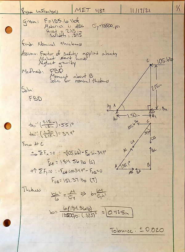
Analysis A-11 illustrates the calculations done to determine the forces acting on the shock mount. The free body diagram was used along with method of joints to solve for the force acting on BC which is in tension. The material specified is ABS which gave a nominal thickness of .425 in. This analysis used the forces based on the two foot drop test making it a critical piece to maintaining the strength of the truck.
Analysis A-12
Pushrod Diameter

Analysis A-12 depicts the necessary calculation to find the nominal pushrod diameter. The pushrod was assumed to be pinned at both ends giving a k factor of 1. The Pcr was found to be 160lb which became 320lb due to a safety factor of 2. The pushrod nominal diameter was found to be about .077 in which was rounded up to a standard size of .100 for ease of purchase. The pushrod transfers energy from the lower control arm to the rocker arm making it a critical component in the drop test which it has been designed to withstand.