
CONSTRUCTION
Many of the parts for the RC Baja require similar tools and operations which allows the engineers to get familiar with the machine shop and the machines available to them.
Using the CNC Plasma Cutter, the chassis plate was cut out of the aluminum stock. The SolidWorks file for the chassis plate was exported in .DXF format to be read by the Torchmate program. With the imported file, the operation was begun which can be seen in Figure 1, above.
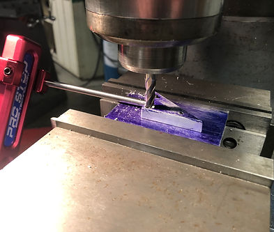
One of the most common operations that have been used is drilling. Pictured above in Figure 2 is the process of drilling the pivot hole for the rocker arm. This task has been used for all of the holes drilled currently for all four rocker arms.
Another common operation after drilling holes has been the use of the vertical tapping machine. This allows the part to be clamped into a table vice where a tap fixed in the end of a shaft is descended into the drilled hole. The shaft is rotated manually and has a counterweighted arm attached to it to ensure that the force applied to the part while tapping is consistent. Using this tool also ensured that the threads in the rocker arms were truly straight as apposed to hand tapping which can be difficult to align correctly.
The Bridgeport milling machine has also been used to begin the process of counter-sinking holes into the rocker arms pivot location where the a bearing will be press fit. Due to the tight tolerances involved in press fits, the milling machine is used with both a square 5/16" end mill as well as a 5/16" reamer to ensure that the bearing will be seated nicely in the pocket.
Methods
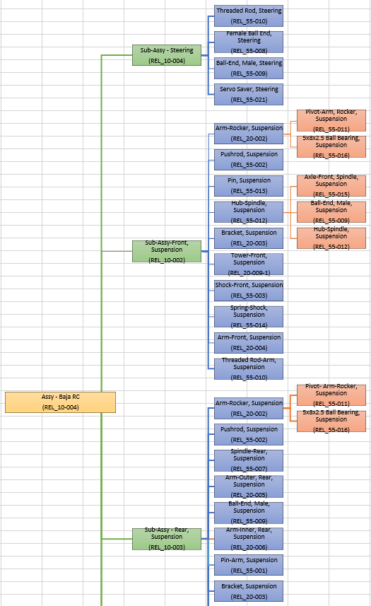

Drawing Tree

Fig. 1 - Chassis plate being cut by CNC Plasma Cutter.
Fig. 2 - Chassis plate being cut by CNC Plasma Cutter. (VIDEO)
Plasma Cutting
Chassis Plate Cutting
A 1-inch diameter flat end mill was used on the manual milling machine to acheive the radial dimension on the side of the rocker arms.
The dimension was to have a 0.7 inch radius however, the largest and closest size found was used. Multiple passes were made to achieve the nominal depth as well.
Milling
Rocker Arm Radius Milling
A 1-inch diameter flat end mill was used on the manual milling machine to acheive the radial dimension on the side of the rocker arms.
The dimension was to have a 0.7 inch radius however, the largest and closest size found was used. Multiple passes were made to achieve the nominal depth as well.
Fig. 3 - Rocker Arm Radius being milled on the manual milling machine (VIDEO)

Fig. 5 - Rocker Arm pivot hole being drilled with a #36 drill bit on the Drill Press.
.jpeg)
Fig. 4 - Finished Rocker Arm radius post milling operation.
.jpeg)
Fig. 6 - Using the table mounted locator, the rocker arm is positioned to have the bearing pocket hole milled.
Fig. 7 - Front Tower being 3D printed (VIDEO)
.jpeg)
Fig. 8 - Front Tower after removed from 3D printing surface and support material removed.
3D Printing
3D Print of Front Suspension Tower
Manufacturing methods like 3D printing, allowed many of the parts to be rapidly produced. It is a process that requires few little input after the model is completed which minimizes risks involved in manual fabrication methods.
The front tower was modeled in SolidWorks to then be exported as a .stl file to be read by the 3D printer program. The process of printing is shown in fig. 6 and fig. 7.
Assembly
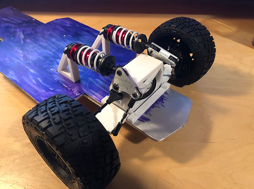
Assembly of the Front Suspension Sub-Assy
Assembly of the front suspension sub-assembly begins with the mounting of the shock mounts and suspension brackets to the chassis. This is followed by the front tower and lower control arms. Next is the left and right spindles with the respective camber arms.
.jpeg)
Fig. 10 - Partially assembled front suspension on chassis plate
.jpeg)
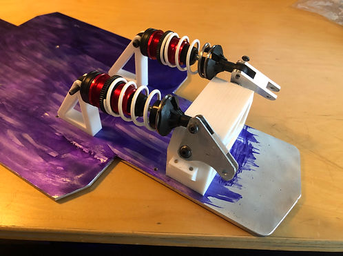
Fig. 11 - Fully assembled front suspension
First Assembly
.jpeg)
Fig. 12 - First Assembly of the chassis, suspension, and steering sub-assemblies.
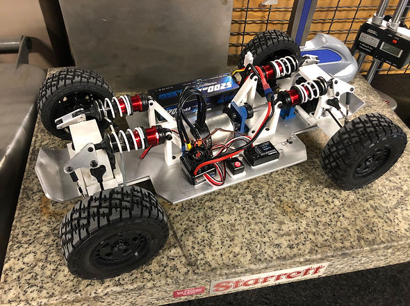
Fig. 13 - Fully assembled RC BAJA Vehicle


